Effective cutting chip control should avoid causing damage to the workpiece, tools, and operators; prevent production interruptions; and eliminate chip disposal issues.

What factors affect chip formation?
Good chip formation can produce spiral short chips, which are generally believed to ensure longer tool life, easier chip handling and disposal, higher surface quality of machined parts, and a stable, reliable, and efficient cutting process. Simply put, ideal chips should be of a manageable size and require minimal effort during their formation.
In practice, numerous factors influence chip formation, including the shape of the tool, cutting conditions, material of the part, and cooling method.
Factors related to part material include the hardness and tensile strength of the workpiece, ductility, and structural considerations. These factors cannot be modified, but their impact on cutting chip formation must be considered.
The influence of the cooling system on chip formation is quite variable. Key tool characteristics include rake angle, cutting edge angle, tool nose radius, and the geometry of the cutting edge and chip breaker groove. Larger rake angles, lower cutting edge angles, and larger tool nose radii tend to produce longer chips. The effect of the coating type on chip formation is not easily defined.
Cutting conditions can intuitively affect chip formation, and altering these conditions is both easy and effective. The primary cutting condition to adjust is the chip thickness ratio or aspect ratio. When the chip thickness ratio is too low, so-called square cutting chips are produced, which impose excessive load on the tool tip, significantly limiting tool life. An excessively high chip thickness ratio results in long, ribbon-like cutting chips that are difficult to break into shorter pieces.
The chip thickness ratio is defined as the cutting width divided by the chip thickness. For a given feed rate, the cutting depth should be sufficiently large to avoid excessively low or high chip thickness ratios. Small cutting depths combined with certain feed rates produce square chips. Conversely, excessively small feed rates can lead to unbreakable ribbon-like chips.
In practical operations, cutting depth is usually fixed. In this case, the feed rate becomes crucial for good chip formation. Avoiding excessively low feed rates prevents long ribbon-like chips, while avoiding excessively high feed rates prevents the formation of square chips.
Chip Morphology
Cutting chips can be defined into four different types based on their cross-section:
Serrated, segmented, or discontinuous chips
Serrated or segmented cutting chips, also known as discontinuous chips, are semi-continuous chips with large areas of low shear strain and localized, small areas of high shear strain. This type of chip is commonly observed when machining materials with low thermal conductivity and strong strain-hardening characteristics. For example, when machining materials like titanium, the strength of the material increases under stress, especially under the combined effects of high temperature and stress. The appearance of these cutting chips is characterized by a serrated pattern.
Continuous cutting chips
Continuous chips are typically produced when machining ductile materials, such as low-carbon steel, copper, and aluminum alloys. Continuous cutting chips are difficult to handle and dispose of, as they can form very long spirals or coils around the workpiece and tool, posing a potential hazard to operators when they break. The prolonged contact time with the tool surface generates more frictional heat. Using chip breakers can effectively address this issue.
Built-up edge chips
When small particles of the workpiece material adhere to the cutting edge of the tool, a so-called built-up edge (BUE) is formed. This primarily occurs with soft and ductile workpiece materials, especially when forming continuous cutting chips. BUE can affect the cutting performance of the tool. These accumulations are very hard and brittle, and as layers of material build up, their stability decreases. When the BUE eventually breaks off, part of it is carried away with the chips to the tool surface, while another part remains on the machined surface, increasing surface roughness.
By increasing the cutting speed, using tools with a positive rake angle and sharper edges, applying coolant, and selecting cutting materials with lower chemical affinity to the workpiece material, the formation of BUE can be effectively reduced.
Shear chips
Shear chips or short chips, also known as discontinuous chips, consist of small segments that are separated from each other. These chips typically form when machining brittle materials such as bronze, hard brass, gray cast iron, and materials that are very hard or contain hard inclusions and impurities. Brittle materials lack sufficient ductility for significant plastic deformation during chip formation, leading to repeated fracturing that limits the extent of chip deformation.
Short chips
In less stable machine tools, short cutting chips may cause micro-vibrations during the machining process due to their intermittent formation. One advantage of these chips is that they are easier to handle and clean. When these chips form in brittle materials, such as bronze and gray cast iron, they often result in good surface finish, lower power consumption, and reasonable tool life. However, for ductile materials, discontinuous chips can lead to poorer surface finish and increased tool wear.

Cross-sections of different chip forms

Examples of chip and built-up edge (BUE) formations under different cutting speeds and chip forms in various workpiece materials:
1.Continuous Chips in Carbon Steel
2.Serrated Chips in Duplex Stainless Steel
3.Built-Up Edge (BUE) in Carbon Steel
4.Carbon steel can develop built-up edge (BUE) chip
Discontinuous Chips in Cast Iron
Cast iron typically forms discontinuous cutting chips, consisting of fragmented segments. This occurs due to the brittle nature of cast iron, limiting its ability to form continuous chips during machining.
Geometric Shapes of Chip Breakers
Long and continuous cutting chips can adversely affect machining efficiency and pose risks of damaging tools, workpieces, and machine tools. Moreover, issues with cutting chip disposal can lead to unnecessary downtime during production and pose safety hazards to operators. To ensure safety, facilitate chip handling, and prevent damage to machine tools and workpieces, it’s crucial to break these long cutting chips into smaller segments.
Chips bend or curl during formation due to various factors, including:
1.Stress distribution within primary and secondary shear zones.
2.Thermal effects.
3.Strain-hardening characteristics of the workpiece material.
4.Geometric shape of the cutting tool.
The influence of the cooling system also plays a role to some extent.
In essence, reducing the rake angle (using tools with a negative rake angle) tightens the curvature of the cutting chips, making them shorter and more prone to fracture. The function of a chip breaker is to reduce the curvature radius of the cutting chip, thereby promoting the fracture of cutting chips into shorter segments.
Basic principles of chip breaker groove geometry
The chip break diagram (refer to the diagram below) illustrates the relationship between workpiece material, cutting conditions, chip breaker type, and cutting chip morphology. This diagram indicates factors to consider when selecting cutting depths and feeds to use specific chip breaker types for machining workpiece materials.
The horizontal axis represents the feed rate, which must always be greater than a certain minimum value (the width of the T-land geometry) and should be less than a maximum value (not exceeding half of the tool nose radius). The vertical axis shows the cutting depth, which should always be greater than the tool nose radius to promote good chip formation and avoid square chip issues. Additionally, the cutting depth should not exceed the cutting edge length. In the latter case, a safety factor is recommended, depending on the strength of the cutting edge. For blades, these safety factors vary between 75% of the cutting edge length (for square or rhombic blades) and 20% (for replica blades with smaller top angles).

Cutting depth and feed rate (referred to as chip thickness ratio) must be kept within certain limits. The maximum chip thickness ratio should be maintained below a certain maximum value to avoid excessively long ribbon-like chips. The chip thickness ratio should also be maintained above a minimum value to prevent square chips from forming. These limits are depicted in the diagram with two diagonal lines. The minimum and maximum values of the chip thickness ratio depend on the workpiece material. To minimize cutting edge damage, cutting forces should not be too high. This constraint is represented by a curved line in the diagram.
Within the blue region of the diagram, every combination of feed rate and cutting depth can produce properly shaped chips. Choosing combinations outside the blue region will result in improper chip formation and may lead to excessively long or square chips, or excessive cutting edge damage.
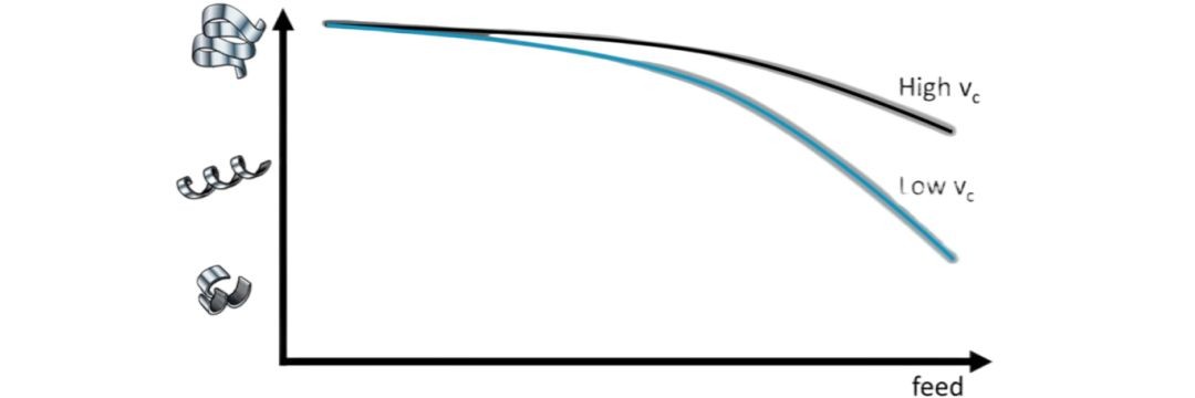
The diagram above illustrates the influence of cutting speed on chip formation. The horizontal axis represents the feed rate, and the vertical axis represents the type of chip. Typically, as the feed rate increases, chips tend to become shorter, especially at low cutting speeds. However, as cutting speed increases, the relationship between feed rate and chip formation diminishes.
Five Methods for Optimizing Chip Control
1.Determine the priority criterion for process optimization: productivity or cost considerations.
2.If the chip shape is acceptable, go to step 5.
If the chips are too long, go to step 3.
If the chips are too short, go to step 4.
3.If productivity is key, increase the feed rate.
If cost efficiency is key, switch to a stronger chip breaker.
Keep the feed rate within the chip breaker’s range.
Go to step 5.
4.If productivity is key, switch the chip breaker to a sharper one.
If cost considerations are key, reduce the feed rate.
Keep the feed rate within the chip breaker’s range.
Go to step 5.
5.If cost considerations are prioritized, reduce the cutting speed.
If productivity is prioritized, increase the cutting speed.
