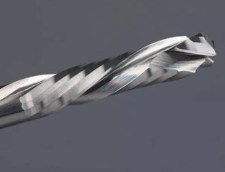
1. Form the design concept and improve the overall strategy.
The process of mechanical design is often from the whole to the local refinement. The so-called whole refers to a general overall view. For example, when you get a topic (designing a machine with a certain function), you should first form an overall fuzzy design concept in your mind (at this time, you should consider some overall factors). For example, the material (physical properties / hardness / strength / yield point / wear resistance / toughness / specific heat / density…) and shape (plate or profile or casting forging…) of the material to be processed by the customer should be considered.
Another example is to consider the overall size, total height, total length and total width of the machine tool you are going to design. In consideration of these basic elements of the general direction, we should also consider the preliminary realization of the machine tool function. That is to say, what kind of process or method should be adopted for forming? As far as the current forming methods are concerned, it can be divided into the ways of not removing materials, removing materials and increasing materials.
The ways of not removing materials are: casting / forging / extrusion / cold rolling / bending / rolling / rounding / bending / spinning…
The ways to remove materials are: turning / milling / drilling / planing / grinding / broaching / sawing / slotting / stamping / cutting / laser cutting / water cutting / flame cutting / plasma cutting / spark erosion.
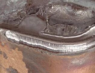
The ways to add materials are: Welding / layered contour processing (3D printer)
In so many molding methods, learn from and determine the most appropriate molding method as the most basic theoretical framework of the machine tool to be designed.

2. Determine the preliminary structure of the machine tool.
Based on the above contents, a preliminary layout plan of machine tool structure is determined. For example, the material to be machined by the machine designed by you is a long profile similar to I-beam (at this time, we should consider the convenience and safety of customer’s loading and unloading in machine tool processing, and consider whether the customer is single processing or multiple processing in bundles at the same time.)
In this case, we may be inclined to determine that the general design idea is to adopt the initial strategy of tool and tool assembly movement (such as laser cutting machine) while the workpiece is fixed (stationary).
Of course, combined with the actual situation can also take the form of table (material) movement (such as gantry milling machine). With a rough preliminary strategy, then we need to consider the production efficiency and accuracy requirements of machine tools. For these two requirements must be combined with equipment cost to determine. For example, whether to adopt the multi station structure, whether to adopt the multi head structure, whether to speed up the work or fast forward speed of each part (the higher the speed, the greater the power requirement for the drive, but also consider the higher the speed, the greater the inertia of the mechanism, and the lower the positioning accuracy. If the motor with large power and inertia is adopted, it will directly mean the increase of the cost.)
At this time, the rigidity of the whole machine tool and the center of gravity should also be considered, or the necessary structural resonance frequency should be considered. At the same time, we should also consider the requirements of ergonomics. (for the operation position or some positions that need to be adjusted and operated frequently, the convenience of normal people should be considered.)
3. Determine the structure and function of each component or assembly.
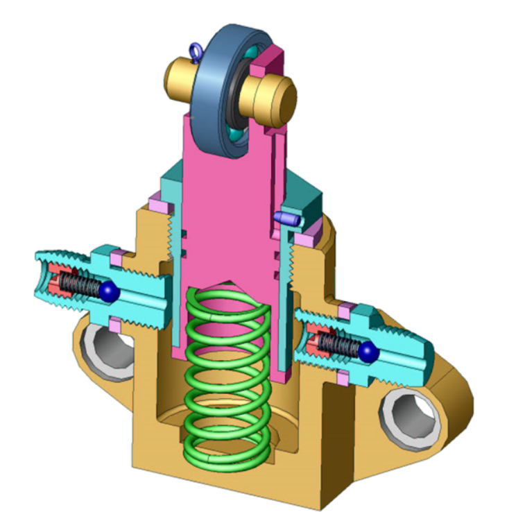
After determining the forming mode and the overall preliminary structure of the machine tool, it is necessary to make a preliminary planning for each part. At this time, it is necessary to make clear the functions of each part and determine which mechanism is used to realize the functions of these parts. The premise of making these plans is to consider the installation and disassembly of the components.
For example, for wearing parts or consumables or for some devices and institutions that need to be adjusted frequently, reasonable convenience of disassembly and maintenance is required. For example, if you want to replace a V-belt, you need to remove and replace the machine in the form of killing cattle and peeling, which is not a good design.
For example, when we decide to use the commonly used linear feed mechanism, we should consider the following aspects: (combining with the actual efficiency and accuracy requirements, we should define a certain form of realization, of course, the commonly used form is the guide rail plus screw, and the sliding friction screw or rolling friction screw should be determined according to the actual situation.
Transmission efficiency, positioning accuracy, dynamic response, load condition, speed characteristics, thread angle, axial load that the lead screw can bear, lead, cost, etc. should be considered comprehensively.) Another example is intermittent motion mechanism. Before the motor control technology is perfect, there are many kinds of mechanisms to realize this kind of mechanism.
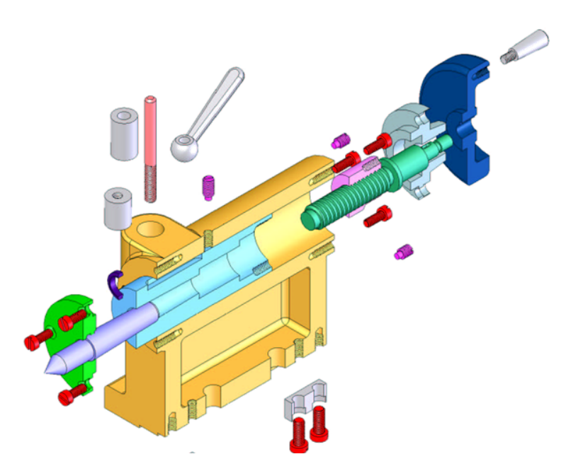
(groove wheel form, incomplete gear form…) The owner thinks that it is difficult to design machinery how to simplify complex problems. For those mechanisms with great efforts, such as cylindrical / disc cam mechanism, strange spatial mechanism, variable four bar mechanism, and incomplete gear mechanism and special gear mechanism which test the manufacturing personnel, etc…..
For deliberately to make some people play not to turn, the situation of the design, the owners do not agree. Of course, the premise is that we can use one-dimensional linear motion or two-dimensional plane interpolation or three axis linkage to solve the problem.
The servo motor and linear rolling friction drive and guide device can perfectly solve the problems that need intermittent, accelerated, stroke amplification and special motion curve. Why should we make those complicated, difficult and non-general ones, dazzled the maintenance and assembly personnel, and most of them are sliding friction mechanisms? Some people may say that a set of 2-D plane linear interpolation platform has obliterated many predecessors who can really call the essence of mechanical design.
For this, class is a very ironic joke. (a new soldier has been trained in field survival, and has been rubbing wood for hours hungry, or he has not been able to drill and fire like his ancestors. After exhausted, I feel the lighter and cigarette. First, I sit on the stone and smoke a cigarette. Then I will take a slow breath and continue to ponder the skill of making fire by drilling and burning the wood…)
Of course, for some necessary and necessary institutions, it is still impossible to fully adopt modern fast food design culture to fill and realize. For example, the vibration characteristics are obtained by eccentric device or the quick locking device on the clamp. Or, the overrunning clutch should be used to get reverse failure and other working conditions.
4. Part design.
First, consider the manufacturing batch of the part. (if a part is manufactured in large quantities, the positioning benchmark and process hole used in the machine tool fixture shall be fully considered.)
Second, the characteristics of the forming mode of the part are considered. (for example, when casting is adopted for a high-speed rotating disc part, there will be some defects such as loose structure or porosity, etc. if the process features are not treated with the later dynamic balance, it will inevitably lead to excessive centrifugal force under the high-speed operation state, and indirectly the bearing will generate heat, abnormal noise, short life and other phenomena. For example, it is easy to “be quenched” in the cutting place when cutting the raw materials of medium carbon steel or high carbon steel to obtain the parts blank.)
Third, consider the raw material characteristics of the part. (for example, for a sheet metal part, we first think of using iron plate to pick up materials, of course, the way to take materials can be laser cutting / water cutting / flame cutting / even wire cutting / or stamping…)… This is decided by combining the best economic benefits of the part. Of course, whether it is for plate or wire, whether it is sawed or cut by flame or laser or water… Pay attention to the problem of discharging. (pursue maximum utilization of materials)
Fourth, consider the processing fixture of the part. (for small batch manufacturing of single piece, some cases that cannot be processed on general machine tools shall be avoided in design, and special clamps must be used for production and processing.)
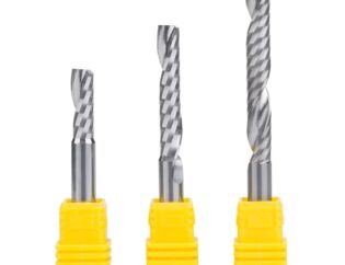
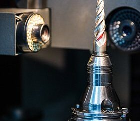
Fifth, consider the tool that makes the part. (when designing parts, the tools that can be purchased in the market and suitable for clamping and using of their own machine tools shall be fully considered. Avoid customizing non-standard tools as much as possible. This part requires a brief understanding of the national standards for some tools. For example, you have designed a hole in the part, and the hole has higher requirements for cylinder and finish.
Generally, we are drilling or turning holes – reaming or boring – or inner circle grinding. But if you choose the diameter of the hole to be close to the first or second series of tools, it will be very difficult to buy the corresponding drill reamer in the standard tool market
Sixth, consider the processing range of the machine that processes this part. (all machine tools have fixed processing capacity range parameters. For example, C6132 means that horizontal lathe can achieve the maximum part rotation diameter of 320. M7130 * 1000 represents horizontal axis rectangular table surface grinder, which can be clamped at one time to grind a plane with width of 300 and length of 1000. Therefore, in the design of parts, it is necessary to consider the clamping or machinability of the machine tool in combination with these machine parameters.)
Seventh, consider measuring tools. (after the part manufacturing is completed, it is required that the general inspection tools and measuring tools can be used for measurement. For example, if you don’t choose standard Morse series or commonly used taper such as 7:24 or 1:50 instead of 7:23 or 1:47, you can’t buy standard taper rod and taper sleeve in the standard measuring tool market. Of course, if the two-dimensional projection detection or three-dimensional detection of parts is not within the scope of this constraint.)
Eighth, consider the heat treatment requirements. (for some new friends, when dealing with parts that need high wear resistance or good comprehensive mechanical properties, such technical requirements often appear on their drawings. The hardness of Q235 quenched material reaches HRC60, and the hardenability and hardness should be uniform.)… Material 45 × steel – 58 HRC after quenching and tempering. For this kind of phenomenon, we can only recommend you to turn over the knowledge of metal materials and heat treatment.) ?
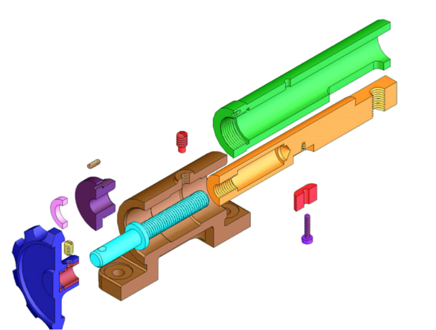
Combined with the actual situation of many “Shanzhai” small workshops in China, the standardization of design drawings is a contradictory problem. According to the normal, standardized, rigorous and scientific methods and methods, the technical department of a production machinery and equipment factory should have full-time drawing personnel, drawing review personnel, process planning personnel, tooling and fixture production personnel, as well as full-time electrical engineers, hydraulic and pneumatic engineers or programmers.
However, under the leadership of “small-scale peasant consciousness”, after being condensed and then compressed, it is often reduced to the situation of one or two people. In addition, one or two of them may be required to complete the work of the above positions, and at the same time, they may also be required to issue the equipment instructions, update and arrange the product samples, prepare the tender documents, and so on.
Here, we only discuss the problems related to the practicability of drawings based on the above-mentioned situation of one person with multiple abilities. (this may not apply to friends who work in standardized companies with clear division of labor and responsibilities.)
First, as designers, they should be modest and studious, and at the same time, they should have the ability of self-determination and independent judgment.) I believe many friends have a deep understanding of this situation, the boss said so, the workshop director said so, the production manager has another idea, the customer will put forward a “reasonable” request.. If we can’t deal with these opinions or suggestions, the name of the drawing package will gradually change from design version 1 to design version 11.
For this, if our designers can’t handle it well, they will form thinking inertia and dependence. As time goes by, we will enter a dead cycle that we will never struggle out. Boss, workshop director and production manager always think that you are just a dead rat on your waist – pretending to be a hunter.
And you feel that without the freedom of design, you feel that talking with these mud legs is totally unspeakable.. Bound, bound too much, completely imprisoned in finger poking and innumerable aftershocks.
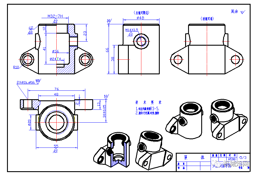
Second, the elements of the drawing should be known as well as the reason. Many novice drawings are often “clean” and “clean”, without roughness mark, shape and position tolerance requirements, no technical requirements of remarks, all line thickness are consistent, missing size, redundant size, closed dimension chain, the drawings can not reflect the processing and measurement datum, n multi dotted line elements and so on.
After working for a period of time, I have a little experience. As a result, the dimensional tolerance and shape and position tolerance requirements indicated in the drawings may appear again, which makes people feel paralyzed at first sight, and then directly paralyzed.
For a simple example, when you design a shaft (in the middle of the bearing), we need to understand that the machining benchmark of the shaft in the final grinding process is the center hole of the two shaft ends. However, when we use the dial indicator to detect the runout of a certain shaft segment after assembly, the measurement benchmark is based on the central axis between the middle bearing position a and bearing position B. therefore, what do you think Can the measuring datum be marked arbitrarily when the runout tolerance of any shaft segment is marked on the drawing?
For another example, when the design of two parts similar to flange connection can not achieve the ideal docking, please do not question the fault of the processing or process arrangement personnel at the first time. You should pick up the drawing you issued and have a close look. Is there no assembly stop? Is there a lack of such technical requirements as “matching”? Is the requirement of screw hole position missing?
6. The soul of design calculation and check
I think the calculations involved in mechanical design can be roughly divided into the following categories:
1. Support the program logic algorithm required by PLC or CNC system or motion control card. A simple example is to solve the algorithm problem of an n-axis linkage manipulator. We need to consider when the arm joint plane moves, the arm joint rotates, the elbow joint plane moves, the elbow joint rotates, the wrist joint rotates, the finger joint swings…. And so on. (this kind of calculation can be classified as the nature of pure mathematical calculation, and physical things are not involved.)
2. Closely related to the calculation of physical phenomena. Such as statics, mechanics of materials, elasticity, fluid mechanics
When designing a part, we should first consider what tasks the part has to undertake or complete, and then combine these tasks to determine the shape of the part, determine the shape and the motion relationship dimensions that need to be satisfied, and then according to the stress state, stress properties and material of the part, at the same time, consider many factors such as rotational speed / thermal deformation / and design life and so on Start to determine the shape and size of each part.
3. Calculation of working hours and process parameters for parts or components processing or assembly. For example, in manufacturing a certain type of equipment, the iron plate blanking part needs to calculate the iron plate layout. The gold processing part has different processing parameters calculation for different processing properties and different processing method arrangement calculation… And the processing time required for each step under such process parameters.
Just when I was working on the calculation sheet of a kind of equipment (CNC full-automatic saw blade grinding machine) recently, there were more than ten pages of A4 paper in the derivation part just to solve the functional relationship between the angle / speed of the saw blade and the displacement and rate of change of the grinding wheel (this belongs to the first kind of calculation quality).
The calculation of the bearing capacity of a certain type of equipment workbench under different load properties and the determination of the resonance frequency of an elastic body, which have been done before, belong to the calculation of the second kind of properties. Of course, the third kind of property calculation can be strictly summarized as the category of technology.
It’s like practicing martial arts. If you don’t practice internal skills, you can never reach the level of master even if you practice foreign moves hard and fiercely. So a so-called real mechanical designer must be both inside and outside.
What about our mechanical design colleagues who lack logical thinking? Yes, reverse! It’s looking from the back to the front. Now the software technology and sensor technology are so developed, many times we can avoid that kind of complicated calculation and checking steps.
For example, I want to know the output torque of an output shaft at different speeds. Take a torsion tester directly and connect it to the output shaft to read each speed. What is the power factor of the motor, the friction between the transmission parts, and the acceleration caused by different mass and speed between different transmission parts are considered. Simultaneous interpreting the data from the former will be more accurate and effective.
Of course, the prerequisite is that we should know and understand the basic concepts of physical properties. As for CAE analysis, the building owner has tried and contacted. It is generally felt that CAE analysis is very sensitive to the accuracy of material property data and the normalization of mesh generation and modeling. What’s more, there are too many uncertain factors affecting the final calculation results, such as the rationality of constraints and load layout. Moreover, it is unable to carry out effective verification of theory and practice, and it is limited to work rhythm and self understanding ability Therefore, it is not discussed.
