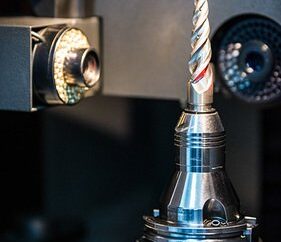
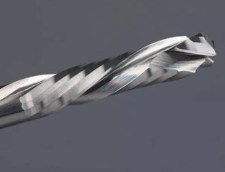
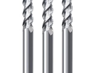
Embracing the trend of three-dimensional parametric design technology, we have shifted to a new model of “parametric design (CAD) – grinding simulation (CAE) – cutting simulation analysis (CAE).” Designers no longer need to physically manufacture prototypes; instead, they can create the three-dimensional solid model of the tool by adjusting geometric parameters. Subsequently, cutting simulation technology is used to evaluate the performance of the design parameters, thereby optimizing the structural parameters of the tool. This transformation has significantly reduced research and development costs and cycles, injecting formidable competitiveness into tool manufacturing companies. Therefore, delving into the research of tool parametric design technology is of self-evident significance.
Techniques and Research Status Related to the Parametric Design of end milling?Cutters
The parametric design of integral end milling?cutters refers to the automatic and rapid generation of a three-dimensional solid model of the end milling?cutter by inputting structural dimension parameters such as the tool’s front angle, back angle, helix angle, diameter, and cutting edge length. To achieve the three-dimensional parametric design of end milling?cutters within a computer, it is necessary to first establish a mathematical description model of the cutter’s structural features. By employing theories and methods related to computational geometry, computer graphics, and Boolean operations, the modeling, display, and storage of the end milling?cutter in the computer are realized. Finally, the development of the parametric design software system is completed through the creation of a user interface and database. Therefore, the main research content of the parametric design of integral end milling?cutters includes the establishment of mathematical models and the software implementation.
The mathematical modeling of integral end milling?cutters involves using mathematical expressions of points, lines, or surfaces to describe the dimensional structure and topological relationships of each spatial structure of the end milling?cutter. The description method will directly determine the precision of the end milling?cutter model and the ease of software implementation. Currently, research on the mathematical modeling of end milling?cutters primarily includes structures such as bar stock, helical cutting edges, and chip flute cross-section lines.
Bar Stock Mathematical Model
As the manufacturing blank for integral end milling?cutters, the bar stock determines the basic structural parameters of the cutter, such as diameter and cutting edge length, as well as the selection of the tool holder. The mathematical model of the bar stock mainly includes two parts: the detailed modeling of the shank and the modeling of the cutter’s rotational contour. By dividing the end milling?cutter body into the shank, neck, and working parts (including the stem and head), and considering the features of the cutter’s shank (taper shank, straight shank, presence or absence of a positioning slot) and head features (rounded, ball-end, chamfered), a general mathematical model for the end milling?cutter bar stock is obtained based on the universal rotational body mathematical model, as shown in Figure 1.

Helical Cutting Edge Mathematical Model
The helical cutting edge curve of an integral end milling?cutter can alter the chip flow direction, increase the actual cutting rake angle, and extend the length of the cutting edge involved in cutting simultaneously, thereby improving the surface machining quality of the workpiece and the tool life. Therefore, the design of the cutting edge curve plays a crucial role in the design of end milling?cutters. The cutting edge curve of an integral end milling?cutter mainly consists of two parts: the peripheral cutting edge curve and the bottom cutting edge curve (for ball-end mills).
The helical cutting edges of end milling?cutters mainly come in three forms:
1.Constant pitch helical cutting edges, where the helix angle with the generatrix is a constant value, and the helix angle with the axis is also a constant value.
2.Based on the concept of helical motion, the method for establishing the geometric equations of constant pitch helices is discussed.
3.Using the velocity method and according to the theory of generalized helical motion of points and lines on any rotational surface, a generalized helix angle mathematical model is proposed, which relates the tangential velocity of a point undergoing helical motion to the angle between the generatrix of the rotating body, as well as the generalized helical line mathematical model. Furthermore, the mathematical models for constant pitch, constant helix angle, and general helical cutting edge curves on conical, spherical, and planar surfaces are derived, as shown in Figure 2.
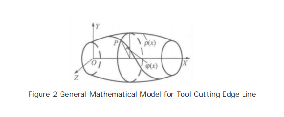
From Figure 2, the general mathematical model for the helical cutting edge can be obtained:
![]()
where p(x) can be determined based on the shape of the milling cutter’s outer contour, and p(x) takes different values depending on the type of helix:
![]()
For equal-pitch cutting edges,?P is the pitch, and φ0 is the initial angle.
![]()
β is the angle between the helix and the generator of the cutter’s rotational body.
The bottom cutting edge curve of a ball-end end milling?cutter mainly includes three forms: straight cutting edge, equal helix angle edge, and orthogonal helical edge (equal pitch edge).
① A straight cutting edge refers to the cutting edge along the axial direction of the cutter’s ball-end portion being in a “straight line” shape. The straight cutting edge has a simple shape and is easy to sharpen, but during machining, it tends to have poor cutting stability due to sudden engagement and disengagement, and the cutting speed at the top of the edge is zero, which can lead to the formation of built-up edge at the top of the cutting edge. Therefore, in actual production, the bottom cutting edge of ball-end end milling?cutters often uses a helical cutting edge, as shown in Figure 3.
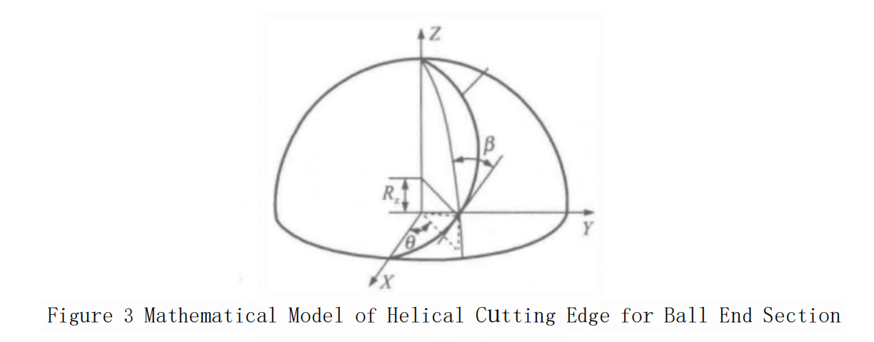
Based on the first fundamental form of the spherical surface, the equation for the equal helix angle helical cutting edge on the ball-end portion is obtained:

Where R? is the parameter and β is the helix angle. When the cutting edge curve is at the top of the ball-end mill, i.e., R = R?, the above equation does not hold, and a separate smooth curve that connects to the vertex needs to be designed.

An orthogonal helical cutting edge refers to the intersection line between the orthogonal helical surface formed by the straight generatrices always perpendicular to the axis of the mill and the spherical surface. Based on the equation of the spherical surface and the equation of the orthogonal helical surface, the equation for the orthogonal helical cutting edge is obtained:
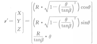
Here, β represents the helix angle of the circumferential cutting edge, θ is the parameter, with 0 ≤ θ ≤ tanβ.
Mathematical Model of Radial Section Lines for end milling?Cutters
The actual chip flute of a end milling?cutter is produced by the grinding wheel moving in a helical path around the cutter’s axis, resulting in a space helical surface. The shape of the radial section line is influenced by the shape of the grinding wheel, its relative position and posture to the cutter, and the relative motion trajectory, making it difficult to precisely describe the section line shape with a mathematical model.
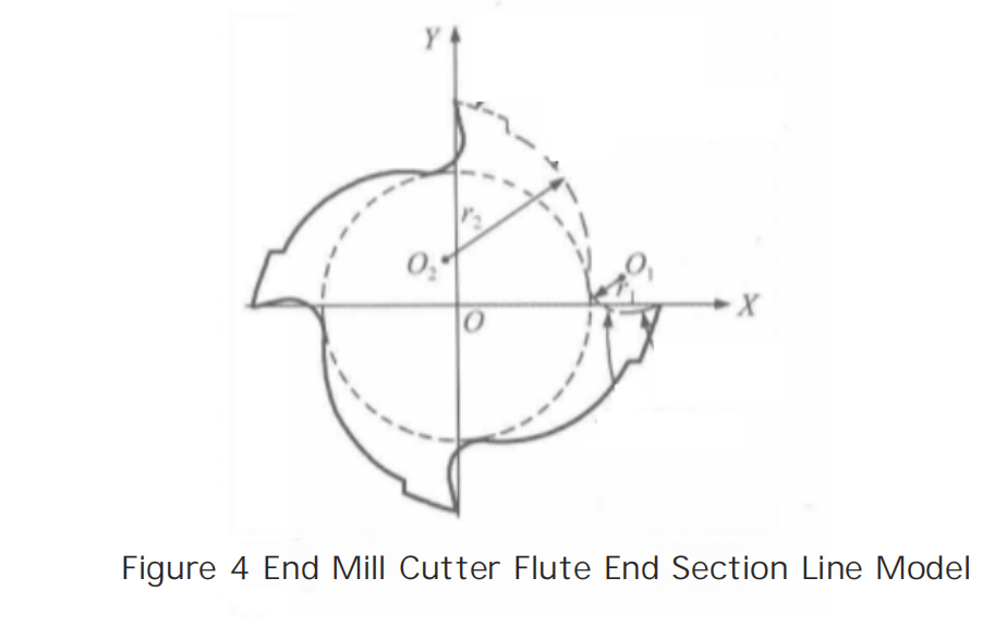
To simplify the calculation, during the parametric modeling of the cutter, the chip flute section line is divided into several parts: the cutting face, the flute bottom, the transition face, and the back face. The cutting face is simplified to a straight line segment, the flute bottom and the transition face are simplified to two arcs, and the back face is simplified to a straight line segment. Among these, the arc representing the flute bottom is tangent to the straight line segment of the cutting face, the core circle, and the transition face. The transition face is tangent to both the arc of the flute bottom and the straight line segment of the back face, as shown in Figure 4.
Research Status of Parametric Design Software for Integral end milling?Cutters
Parametric design software for integral end milling?cutters requires a user-friendly human-machine interface as well as the capability to display and store three-dimensional models of the cutters. Currently, there are mainly two development approaches: secondary development technology based on existing 3D CAD software and development technology based on the OpenGL graphics interface.
By utilizing the secondary development interfaces provided by software such as UG, SolidWorks, CATIA, Pro/Engineer, and AutoCAD, and calling library functions for modeling, transformation, and Boolean operations, the parametric design of end milling?cutters can significantly reduce the programming difficulty of the software system. To date, universities such as Shandong University, Southwest Jiaotong University, Northwestern Polytechnical University, Harbin University of Science and Technology, Xihua University, Northeastern University, and Xiamen University have conducted extensive research on the parametric design of end milling?cutters based on secondary development technology of 3D CAD software.
Parametric Design of Cutters Based on UG Secondary Development Technology
Shandong University has established a parametric design system for solid carbide end milling?cutters based on the grinding and manufacturing process of the cutters. They used UG/Open MenuScript to create system menus, UG/Open UIStyler to create a user interface in the UG style, and UG/Open GRIP along with UG/Open API for secondary development functions to create the three-dimensional solid model of the end milling?cutter. They compiled the program using VC++ and completed the development. Subsequently, they studied the modeling methods for detailed structures such as the tip radius and relief grooves and completed the development of two-dimensional engineering drawings. They also established three-dimensional models for milling cutters with unequal pitch. Northeastern University, based on the theory of helical lines and helical surfaces, completed the parametric design of end milling?cutters and forming cutters for machining chip flutes after classifying and analyzing the characteristics of CNC helical milling cutters. Northwestern Polytechnical University conducted parametric design for indexable cutters and flat-end end milling?cutters. Harbin University of Science and Technology established mathematical models for the helical lines and chip flute section lines of ball-end end milling?cutters and carried out parametric design for integral ball-end end milling?cutters. Xiamen University added a model for relief grooves, achieving the design of tapered ball-end milling cutters.
Parametric Design of Cutters Based on SolidWorks Secondary Development Technology
Xihua University and others, to meet the needs of Zigong Cemented Carbide Co., Ltd., have developed an object-oriented three-dimensional parametric cutter CAD system using SolidWorks as the development platform and VC++ as the development tool. By utilizing SolidWorks API for secondary development functions, combining dynamic link library technology, Oracle database technology, and ADO (ActiveX Data Objects) database connection technology, and based on the cross-sectional model of end milling?cutters, they have achieved parametric design for chip flutes, four-edge ball-end end milling?cutters, and indexable ball-end end milling?cutters.
Parametric Design of Cutters Based on CATIA Secondary Development Technology
Southwest Jiaotong University, with the assistance of CATIA/API functions and OLE Automation technology, has chosen Visual Basic (VB) as the development tool to develop a parametric design system for end milling?cutters. This system can realize parametric design for five major types of end milling?cutters, including ball-end end milling?cutters, conventional end milling?cutters, CNC end milling?cutters, high-speed end milling?cutters, and end mills. It can also achieve parametric modeling of solid blanks, cylindrical teeth, ball teeth, end teeth, transition teeth, and other detailed cutter structures.
Parametric Design of Cutters Based on AutoCAD Secondary Development Technology:
Northeastern University has chosen VB as the development tool for secondary development of AutoCAD, completing the development of standardized CAD/CAPP software. This software uses a method of disassembly and simplification, modularizing the structural features of end milling?cutters, and achieving computer-aided design for titanium alloy machining end milling?cutters through the invocation of various sub-modules.
Parametric Design of Cutters Based on Pro/E Secondary Development Technology
Lanzhou University of Technology has used the Pro/Toolkit tool for secondary development of Pro/E. Based on the mathematical models of the cutting edge curve, peripheral flute surface, peripheral relief surface, relief groove surface, and the main spiral?slot, relief surface, and spiral secondary groove surface of the ball-end end milling?cutter, they have achieved parametric design of the ball-end end milling?cutter by using surface merging, arraying, and solidification techniques. Tianjin University of Technology and Shanghai Jiao Tong University have established a parametric design system for two-tooth ball-end end milling?cutters, which includes design tools for the cutter body, chip flute, peripheral relief angle, end tooth rake angle, standard Gash, and end tooth relief angle.


